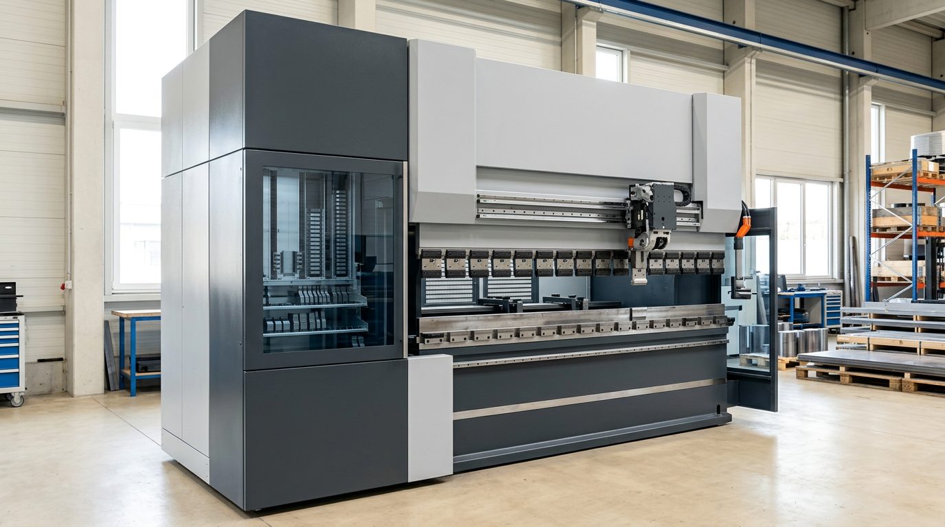
The TRUMPF LASERdur punches, dies and hemming rail we actually own for the machine — every set is on a TRUMPF order confirmation. Design parts around them and they bend without special tooling: V-opening, inner radius, flange length and force decide what can be made. Our calculator uses the same rules.
8 tool setspress force 1700 kNlongest set 2050 mm
Filter by type:
Tool profiles
Cross-sections dimensioned from the TRUMPF 2025 catalogue. The outline outside the dimensioned values is schematic; each tool has its own scale.
Acute angles with the 30° die (bends below 90°), pre-bend and closing of hems on the FWZ rail. Slim profile, small interference contour.
The catalogue (pp. 110, 27) gives 400 kN/m for bending and 1300 kN/m for hemming. Material no. 384444 from the order confirmation (version with horn segments) is not listed in the 2025 catalogue; the dimensions come from the OW210/S H240 catalogue page.
Hemming with lower-tool shift (I axis): 30° pre-bend in the EV004 die, then closing on the rail. Steel and aluminium up to 2.5 mm, stainless up to 2 mm.
Listed in TruTops in two orientations (front and rotated) — it is one set.
What we can bend
90° air bending: for each thickness, the dies of ours that take the bend. Force is the guide value from the TRUMPF press-force table (kN per metre of bend length); the tool load must not exceed the lower rating of die and punch. The highlighted die is the one the calculator picks. 56
Material:
What we can bend — Steel (450 N/mm²) and galvanised sheet
Thickness
Die
Inner radius ≈
Min. flange
Force
Max. bend length
0.5 mm
EV/S W6/84° + OW200/S
R1.4
4.5 mm
28 kN/m
550 mm
0.75 mm
EV/S W6/84° + OW200/S
R1.4
4.5 mm
64 kN/m
550 mm
EV/S W10/84° + OW200/S
R2.1
7.1 mm
36 kN/m
2050 mm
EV004 W12/30° + OW210/S
R2.5
9.3 mm
30 kN/m
2050 mm
1 mm
EV/S W6/84° + OW200/S
R1.4
4.5 mm
131 kN/m
550 mm
EV/S W10/84° + OW200/S
R2.1
7.1 mm
70 kN/m
2050 mm
EV004 W12/30° + OW210/S
R2.5
9.3 mm
57 kN/m
2050 mm
1.25 mm
EV/S W6/84° + OW200/S
R1.4
4.5 mm
204 kN/m
550 mm
EV/S W10/84° + OW200/S
R2.1
7.1 mm
109 kN/m
2050 mm
EV004 W12/30° + OW210/S
R2.5
9.3 mm
88 kN/m
2050 mm
EV W20/84° + OW200/S
R4.1
14.5 mm
50 kN/m
2050 mm
1.5 mm
EV/S W10/84° + OW200/S
R2.1
7.1 mm
157 kN/m
2050 mm
EV004 W12/30° + OW210/S
R2.5
9.3 mm
127 kN/m
2050 mm
EV W20/84° + OW200/S
R4.1
14.5 mm
72 kN/m
2050 mm
1.75 mm
EV/S W10/84° + OW200/S
R2.1
7.1 mm
213 kN/m
2050 mm
EV004 W12/30° + OW210/S
R2.5
9.3 mm
173 kN/m
2050 mm
EV W20/84° + OW200/S
R4.1
14.5 mm
99 kN/m
2050 mm
2 mm
EV/S W10/84° + OW200/S
R2.1
7.1 mm
279 kN/m
2050 mm
EV004 W12/30° + OW210/S
R2.5
9.3 mm
226 kN/m
2050 mm
EV W20/84° + OW200/S
R4.1
14.5 mm
129 kN/m
2050 mm
2.5 mm
EV004 W12/30° + OW210/S
R2.5
9.3 mm
353 kN/m
2050 mm
EV W20/84° + OW200/S
R4.1
14.5 mm
201 kN/m
2050 mm
EV W30/80° + OW200/S
R4.7
23.7 mm
131 kN/m
1050 mm
3 mm
EV W20/84° + OW200/S
R4.1
14.5 mm
290 kN/m
2050 mm
EV W30/80° + OW200/S
R4.7
23.7 mm
188 kN/m
1050 mm
3.5 mm
EV W20/84° + OW200/S
R4.1
14.5 mm
394 kN/m
2050 mm
EV W30/80° + OW200/S
R4.7
23.7 mm
256 kN/m
1050 mm
4 mm
EV W20/84° + OW200/S
R4.1
14.5 mm
515 kN/m
2050 mm
EV W30/80° + OW200/S
R4.7
23.7 mm
335 kN/m
1050 mm
4.5 mm
EV W20/84° + OW200/S
R4.1
14.5 mm
652 kN/m
2050 mm
EV W30/80° + OW200/S
R4.7
23.7 mm
424 kN/m
1050 mm
5 mm
EV W30/80° + OW200/S
R4.7
23.7 mm
523 kN/m
1050 mm
6 mm
EV W30/80° + OW200/S
R4.7
23.7 mm
754 kN/m
1050 mm
What we can bend — Stainless (700 N/mm²)
Thickness
Die
Inner radius ≈
Min. flange
Force
Max. bend length
0.5 mm
EV/S W6/84° + OW200/S
R1.6
4.5 mm
44 kN/m
550 mm
0.75 mm
EV/S W6/84° + OW200/S
R1.6
4.5 mm
99 kN/m
550 mm
EV/S W10/84° + OW200/S
R2.4
7.1 mm
56 kN/m
2050 mm
EV004 W12/30° + OW210/S
R2.9
9.3 mm
46 kN/m
2050 mm
1 mm
EV/S W6/84° + OW200/S
R1.6
4.5 mm
203 kN/m
550 mm
EV/S W10/84° + OW200/S
R2.4
7.1 mm
108 kN/m
2050 mm
EV004 W12/30° + OW210/S
R2.9
9.3 mm
88 kN/m
2050 mm
1.25 mm
EV/S W10/84° + OW200/S
R2.4
7.1 mm
169 kN/m
2050 mm
EV004 W12/30° + OW210/S
R2.9
9.3 mm
137 kN/m
2050 mm
EV W20/84° + OW200/S
R4.9
14.5 mm
78 kN/m
2050 mm
1.5 mm
EV/S W10/84° + OW200/S
R2.4
7.1 mm
244 kN/m
2050 mm
EV004 W12/30° + OW210/S
R2.9
9.3 mm
198 kN/m
2050 mm
EV W20/84° + OW200/S
R4.9
14.5 mm
113 kN/m
2050 mm
1.75 mm
EV/S W10/84° + OW200/S
R2.4
7.1 mm
332 kN/m
2050 mm
EV004 W12/30° + OW210/S
R2.9
9.3 mm
269 kN/m
2050 mm
EV W20/84° + OW200/S
R4.9
14.5 mm
153 kN/m
2050 mm
2 mm
EV004 W12/30° + OW210/S
R2.9
9.3 mm
352 kN/m
2050 mm
EV W20/84° + OW200/S
R4.9
14.5 mm
200 kN/m
2050 mm
2.5 mm
EV W20/84° + OW200/S
R4.9
14.5 mm
313 kN/m
2050 mm
EV W30/80° + OW200/S
R6.5
23.7 mm
204 kN/m
1050 mm
3 mm
EV W20/84° + OW200/S
R4.9
14.5 mm
451 kN/m
2050 mm
EV W30/80° + OW200/S
R6.5
23.7 mm
293 kN/m
1050 mm
3.5 mm
EV W20/84° + OW200/S
R4.9
14.5 mm
614 kN/m
2050 mm
EV W30/80° + OW200/S
R6.5
23.7 mm
399 kN/m
1050 mm
4 mm
EV W30/80° + OW200/S
R6.5
23.7 mm
521 kN/m
1050 mm
4.5 mm
EV W30/80° + OW200/S
R6.5
23.7 mm
660 kN/m
1050 mm
5 mm
our tools cannot take this bend (EV W30/80° 814 > 800 kN/m)
6 mm
our tools cannot take this bend (EV W30/80° 1172 > 800 kN/m)
The rules we check a bend against
V-opening w ≈ 6 × s for 0.5–2.6 mm sheet and 8 × s for 3–8 mm; minimum flange ≈ 0.75 × w (catalogue pp. 300 and 179).
Minimum flange b1 (84°/80° dies) and b2 (30° die) and inner radius Ri from the press-force table; valid for an R1 punch on V6–V40 (p. 301).
Force per metre must not exceed the die rating (p. 300) or the punch rating (p. 27); total force must stay within the 1700 kN press.
84° and 80° dies only for angles of 90° and more; acute angles 30°–90° in the 30° V12 die with the OW210/S punch (p. 178).
Hems: 30° pre-bend, then closing on the FWZ rail with lower-tool shift — steel and aluminium up to 2.5 mm, stainless up to 2 mm (p. 170, handbook p. 138).
Bend length must not exceed the set length: V6 550 mm, V30 1050 mm, all others 2050 mm.
Galvanised sheet: LASERdur ZN coated dies reduce zinc abrasion; our dies are uncoated LASERdur.
High-strength steels (Strenx, Hardox) need a larger punch radius and a wider V, springback is typically 8–15°. The calculator does not assess these materials.
Galvanised sheet is calculated with the 450 N/mm² steel table; the table has no aluminium — the calculator gives no verdict for aluminium.
For every part with bends the calculator shows which die and punch we will use — or says plainly why we can't make the bend.Price a part
Lengths 2050 / 1050 / 550 mm are the total set lengths from the order confirmation; the segment split comes from the TruTops tool list (L100 and R100 are left and right horn segments).
The TruTops list carries an extra value "2" in front of the segments of every tool, which the file does not explain; it is not counted (without it the segments add up exactly to the set length).
Machine installation height 615 mm (catalogue: TruBend 5000 series with increased installation height). All dies have a working height of 100 mm.
The tools are stored and changed by the ToolMaster KB37; upper and lower tool clamping is hydraulic.
Data sources
Every value in the tables points by number to the document it comes from. Prices, serial numbers and personal data are not published.
Potvrzení objednávky 220150971.pdf · 2025-08-05TRUMPF order confirmation for offer 23088957: eight LASERdur press-brake tool sets for the TruBend 5170 (items 200–900), 1 set each, with length and division B/A. Drawn from the tool package of the machine purchase (100 % package discount), so there is no separate invoice.
nabidka_23088957.pdf · 2025-08-05TRUMPF offer "tool set" with the same items as the order confirmation; confirmed in writing the same day.
Improtech.btools · 2025-08-12TruTops tool list with the segment split of every tool; matches the order confirmation item by item.
7.0_Technicko- cenová nabídka TruBend 5170 (B23).pdf · 2025-06-20Signed TRUMPF technical and commercial offer: scope of the TruBend 5170 (B23) including ToolMaster KB37, hydraulic upper and lower tool clamping and the LASERdur press-brake tool package (tools not itemised); press force 1700 kN.
Katalog_OhrNastr_2025_CZ-EUR.pdf · 2025-01TRUMPF LASERdur catalogue 2025: dimensions, angle, radius, working height, max. load, weight and minimum flange of every tool (pp. 27, 76, 110, 173, 191, 202, 205, 217, 222); die selection (pp. 178–179, 300); press-force table with minimum flange and inner radius (p. 301); hemming (p. 170); installation height of the TruBend 5000 (p. 34).
Katalog_BW_5-11-2022.pdf · 2022-11-05Previous catalogue edition (04/2022): the press-force table (p. 237) matches the 2025 edition in the values we use.
1439874_Biegetechnik_tschechisch.pdf · 2016-04TRUMPF bending technology handbook (04/2016): hemming tools and thickness range (p. 138), bending different materials — galvanised and high-strength sheet (pp. 188–191).
What the documents do not state
No TRUMPF invoice lists further press-brake tools; the TRUMPF invoices in the books are for punching tools and spare parts.
TRUMPF offer 23296980 (07/2026) for a radius tool (round-bar holder + W80/40° die) is not yet backed by an order — not included in the list.
The press-force table has no aluminium; the calculator does not assess bends in aluminium.