Bending · press brake
Sheet metal bending: thicknesses, bend radii and tolerances
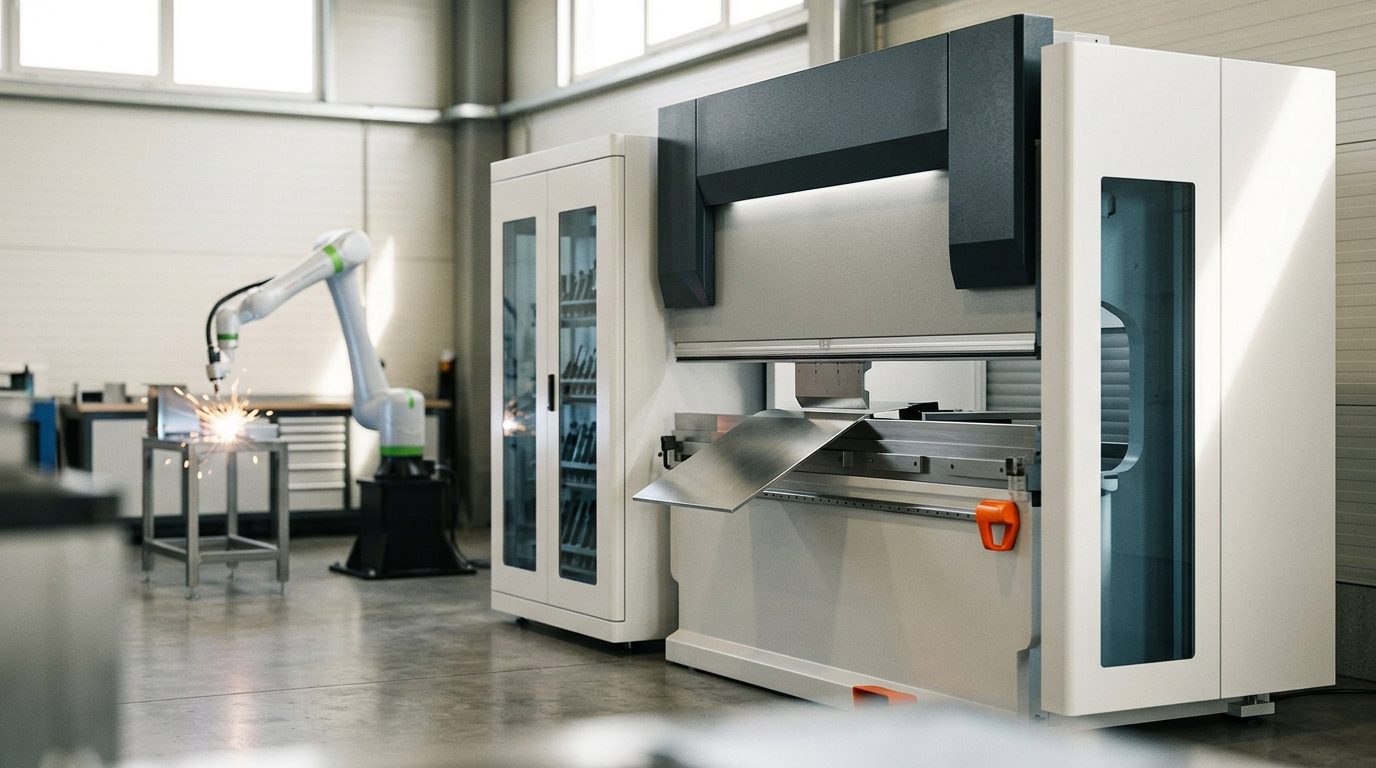
Sheet metal bending is usually the last and most sensitive step in making a sheet metal part — it decides whether the finished cover, frame or bracket fits to the millimetre or has to be laboriously straightened. This page sums up how bending works on a press brake, which radii and distances are worth respecting in the drawing, and what tolerances you can realistically expect from a jobbing shop.
How sheet metal bending works
The flat blank (laser-cut part) is placed on the press brake, where the punch presses the sheet into a V-shaped die. The bend angle is set by how deep the punch travels into the die — modern machines such as the TRUMPF TruBend measure the actual angle during the bend (the ACB Laser system), so the first part is within tolerance without trial-and-error scrap. A five-axis back gauge (X, ΔX, R, Z1, Z2) positions the blank automatically, so even a complex part with many bends comes out repeatably.
The bend sequence is critical. Every bend needs room to clear — the part is turned over after each step, and flanges that are already bent must not hit the tooling or the machine frame. That is why we check the part geometry against the bend sequence in software before the material is even ordered. If a bend is physically impossible, it shows up on screen, not at the press brake.
Thicknesses, bend radii and minimum distances
The most common design mistake is an inside radius that is too small, and holes or embossings placed too close to the bend. Sensible starting values for ordinary steel and stainless steel are:
| Sheet thickness | Min. inside radius | Min. flange length * |
|---|---|---|
| 1.0 mm | 1.0 mm | approx. 5–6 mm |
| 2.0 mm | 2.0 mm | approx. 9–10 mm |
| 3.0 mm | 3.0 mm | approx. 13–15 mm |
* The shortest flange depends on the die used — indicative value. The general rule: keep the inside radius at least equal to the sheet thickness, and place holes or cut-outs at least 2 to 3 times the thickness away from the start of the bend so the edge of the hole is not stretched and distorted. Stronger and harder materials (stainless, spring steels) need a larger radius; low-ductility aluminium tends to crack on the bend, so the radius is increased there too.
We cut and punch the blanks for bending ourselves, from sheet up to 6 mm thick in sheet sizes up to 1250 × 2500 mm. Our modern equipment deliberately covers the thin and medium-gauge segment that our group of companies needs; we do not make parts from thicker plate. For samples and prototypes we recommend our stock materials — stainless steel 1.4307 (304L) in 1 / 2 / 3 / 4 mm, cold-rolled mild steel DC01 in 1.5 / 2 / 3 mm and galvanised steel DX51D+Z275 in 1 / 2 / 3 mm. They are cheaper and available straight away.
Flat length and the K-factor
On the bend, the sheet stretches on the outside and is compressed on the inside; the neutral axis, whose length does not change, lies somewhere in between — its position is described by the K-factor. It is used to calculate the flat length (developed length), i.e. the size of the flat blank that gives exactly the required part after bending. Get it wrong and the part ends up tenths of a millimetre to several millimetres out. A manual calculation is easy to get wrong — in our instant quote calculator the flat length and the price are calculated automatically from the uploaded model.
Tolerances and what affects accuracy
In ordinary jobbing work, the angular tolerance is around ±0.5° and the dimensional tolerance is in the order of tenths of a millimetre per flange. Accuracy depends on the thickness tolerance and rolling direction of the sheet, on springback of the material, on the condition of the tooling and, above all, on whether the blank was cut accurately — bending never fixes an inaccurate blank. That is why sheet metal cutting and bending are closely linked, and it pays to treat them as one production chain.
Frequently asked questions
What is the smallest radius sheet metal can be bent to?
In practice roughly equal to the sheet thickness for softer steel; stainless steel and aluminium usually need more. Below that limit the outer fibres may crack or springback becomes uncontrolled.
Do I need a 3D model for bending, or is a drawing enough?
A 3D model (STEP/STP) works best — both the bend sequence and the flat length are derived from it. For a purely flat part, a DXF of the flat pattern is enough. A dimensioned drawing with angles and radii is a welcome addition.
How thick a sheet can you bend?
We bend parts from sheet up to 6 mm, which we cut ourselves on a machine with a 1250 × 2500 mm sheet format. We do not do thicker plate — thin and medium-gauge sheet is the segment our equipment is deliberately built for.
Can you do a single part?
Yes. Thanks to automatic tool setting (ToolMaster), even a single part or a small batch is economical — there is no expensive set-up as with press tools.
Why is my part not exactly to size after bending?
Most often because of a wrongly calculated flat length or springback of the material. We deal with both by calculating from the model and measuring the angle directly on the press brake.
Have a 3D model of a part to be bent (STEP/STP)? Upload it and see the price and lead time immediately — no waiting for a sales quote.